RA4 is an open-drain output, so it needs a pull-up (depending on load type) If you use it as one of the GPOs then no pullup is necessary (MO-style GPOs).
On the 16F628, RB2 is needed for RS232 transmit if you're using buttons (and might need a MAX232 or similar driver, although it's possible to do RX and TX with just some transistors and resistors).
If the LCD RS, R/W and EN are left on RA0-2 and LCD data bite 4-7 are moved to RA4-7 and RB1=RX, RB2=TX, RB3=PWM, that leaves 6 pins spare: RA3, RB0 and RB4-7.
You could do something like 2 GPOs and 4 buttons (no multiplexing), or even 6 buttons with multiplexing (2x3). I'd prefer to skip the GPOs and have more buttons (eg 2x4=8 buttons).
Matt
Our new official repo is on github
LCD Smartie version 5.6 is released!
Download it now: https://github.com/LCD-Smartie/LCDSmartie/releases
LCD Smartie version 5.6 is released!
Download it now: https://github.com/LCD-Smartie/LCDSmartie/releases
PIC Serial Backpack I - Make your own Serial LCD
Moderators: _X7JAY7X_, caesar, IFR, mattcro, limbo, Fast351, hydrolisk1792
-
ch424
- Posts: 30
- Joined: March 21st, 2006, 6:43 pm
- Location: Oxford, UK
Oops, thanks Matt, I forgot about TX, duh!
A few people on the last page said a buzzer would be cool, so maybe just the one GPO for that? That leaves 5 pins free, so six buttons using normal multiplexing, or eight using the transistor-as-NOT-gate method I posted above. What do you think J? It's your project
ch424
A few people on the last page said a buzzer would be cool, so maybe just the one GPO for that? That leaves 5 pins free, so six buttons using normal multiplexing, or eight using the transistor-as-NOT-gate method I posted above. What do you think J? It's your project
ch424
-
_X7JAY7X_
- Hardware Genie - Plugin Author
- Posts: 374
- Joined: February 16th, 2005, 10:24 pm
- Location: Michigan
Sure, the number of GPOs and Buttons dont really matter to me, thats more up to you guys. I am testing something out right now. I think I need to use 8 bit interface for ALL LCDs. Ceasar pointed out that there is something weird going on with some Winamp screens. I think its because of 4bit mode. If I have to go that route then I will need 11 pins for the LCD. With the PWM and TX, RX, that leaves 3 pins free. Since there are so few pins left. That leaves either all buttons (multiplexed or not) or 2 buttons and one GPO.
What do you guys think?
J
What do you guys think?
J
-
ch424
- Posts: 30
- Joined: March 21st, 2006, 6:43 pm
- Location: Oxford, UK
It took me a while to get 4-bit working reliably, but these are my routines in C and they work with the three (two 20x4s (Batron and Orient) and a 16x2 Batron) LCDs I've tried...
The LCDs seem really picky about the timing and order you change pin states in. When I got winamp spectrum analyser distortion (in both my AVR and PIC implementation), it was because I wasn't waiting long enough between sending commands (even 100us wasn't enough!), or wasn't reading the BF properly.
ch424
-
_X7JAY7X_
- Hardware Genie - Plugin Author
- Posts: 374
- Joined: February 16th, 2005, 10:24 pm
- Location: Michigan
CH424, did you try all of the demo winamp screens? Mine works fine for some, other not so well. It could be the timing, however, most of my LCD functions are built into the compiler. They were set and tested when the compiler was made. Its still possible thats the problem though.
I guess this is why CF and MO use 8bit interface in most (if not all) LCDs.
J
I guess this is why CF and MO use 8bit interface in most (if not all) LCDs.
J
-
Rafael
- Plugin Author
- Posts: 71
- Joined: November 22nd, 2005, 7:12 pm
- Location: Curitiba, Paran?, Brazil
-
_X7JAY7X_
- Hardware Genie - Plugin Author
- Posts: 374
- Joined: February 16th, 2005, 10:24 pm
- Location: Michigan
-
_X7JAY7X_
- Hardware Genie - Plugin Author
- Posts: 374
- Joined: February 16th, 2005, 10:24 pm
- Location: Michigan
Scratch my last few posts. I found out two things: Those cheap USB converters (at least mine) dont work so well. That is where almost all of my garbage was coming from on the winamp screens. The one thing that ceasar pointed out seems to be fine, I just increased the refresh rate in smartie.
All is well now. I will test a bit more tommorrow, but hopefully I am back to where I was. If it fine, next is buttons.
J
All is well now. I will test a bit more tommorrow, but hopefully I am back to where I was. If it fine, next is buttons.
J
-
_X7JAY7X_
- Hardware Genie - Plugin Author
- Posts: 374
- Joined: February 16th, 2005, 10:24 pm
- Location: Michigan
-
_X7JAY7X_
- Hardware Genie - Plugin Author
- Posts: 374
- Joined: February 16th, 2005, 10:24 pm
- Location: Michigan
Just an update.
I have discontinued work on the 4x40 because Ceasar has a PIC version out.
I have been working on the 628 version of the serial lcd. It now supports 4 buttons. I will be working on it on and off over the summer. The next
things will be a GPO or two and multiplexing to allow many more buttons.
Right now the parts count is at 6 pieces for the 4 button version (4 buttons, the PIC, and a resistor) and whatever kind of TTL converter you choose.
If anyone is interested please PM or Email me.
J
-
cruzz
- Posts: 19
- Joined: March 16th, 2006, 11:27 am
- Contact:
Hi again
I succesfully built your seriall version. Now I found link leading to Maxim?s product MAX232. Then I found MAX3325. It looks very interesting, and I think, this could be used to connect LCD display via RS232 as well as your circuit.
http://www.maxim-ic.com/quick_view2.cfm/qv_pk/2117
http://fl.hw.cz/firemni_clanky/hte/maxi ... ax3325.gif
But I am not sure if it is possible. On the picture, there is some circuit and example of connecting LCD, but there is no data wire, only power wires, so I am not sure how to connect it. Would you be so kind and take a look at it? Or if you have some idea or experience with this plz give me some advice. Thx a lot
-
_X7JAY7X_
- Hardware Genie - Plugin Author
- Posts: 374
- Joined: February 16th, 2005, 10:24 pm
- Location: Michigan
I have never used the 3325. Although, from what I see it is very interesting. Among other things, the main purpose of it is that it has temperature controlled LCD contrast. To use it I would start with the schematic you posted in that second link. Use the data lines from the PIC, but the power lines (Vcc, Vee, Vss) from the 3325.
Let me know if that doesnt answer your question.
J
Let me know if that doesnt answer your question.
J
-
cruzz
- Posts: 19
- Joined: March 16th, 2006, 11:27 am
- Contact:
Thx for quick reply. So you think, that this Max is only for controllong LCD?s contrast? I tought it is convertor from RS232 signals to TTL logic, also this MAX232 http://focus.ti.com/lit/ds/symlink/max232.pdf seems like RS232-TTL convertor and not only for power levels, even data bits. On the example at page 7 in that pdf, there you can see 2 RS232 inputs and on the other side, 2 TTL outputs, so in my opinion, this could be used instead your PIC. Sorry, I am not so skilled in this problematic, so if you colud please write me your opinion on it. Thx much
-
caesar
- Forum Supporter
- Posts: 734
- Joined: October 15th, 2005, 10:39 am
- Location: Romania
- Contact:
Hi cruzz!
The MAX3325 is a RS232 (+12V / -12V signalling) to TTL (+5V / 0V signalling) convertor that operates from 3V to 3.6V.
It has LCD 5V power supply of 5V and contrast generator +2V to -5V for extended temperature dot-matrix LCD's.
You still need a microcontroller (PIC or some other IC) to convert the serial data of the COM port to parallel data for the LCD... to use it with LCDSmartie you even have to emulate either Matrix orbital or Crystalfontz protocols for serial communication!
As you have to supply the PIC with 5V and LCD also you will build a 5V system that takes power from the PC so you won't need that MAX3325 that operates at 3.3V to generate +5V for the LCD. As the room temperature is constant you don't need a temperature controlled lcd contrast. MAX3325 is designed for portable applications where the lcd is used over a wide temperature range.
-
cruzz
- Posts: 19
- Joined: March 16th, 2006, 11:27 am
- Contact:
Thx much, its clear nowcaesar wrote:Hi cruzz!
The MAX3325 is a RS232 (+12V / -12V signalling) to TTL (+5V / 0V signalling) convertor that operates from 3V to 3.6V.
It has LCD 5V power supply of 5V and contrast generator +2V to -5V for extended temperature dot-matrix LCD's.
You still need a microcontroller (PIC or some other IC) to convert the serial data of the COM port to parallel data for the LCD... to use it with LCDSmartie you even have to emulate either Matrix orbital or Crystalfontz protocols for serial communication!
As you have to supply the PIC with 5V and LCD also you will build a 5V system that takes power from the PC so you won't need that MAX3325 that operates at 3.3V to generate +5V for the LCD. As the room temperature is constant you don't need a temperature controlled lcd contrast. MAX3325 is designed for portable applications where the lcd is used over a wide temperature range.
-
mattcro
- Forum Supporter
- Posts: 590
- Joined: March 8th, 2006, 1:58 pm
- Location: Scotland
Hey all,
I've been doing some more work on my MO serial implementation, after a lapse while moving house...
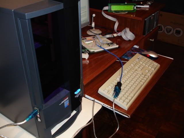
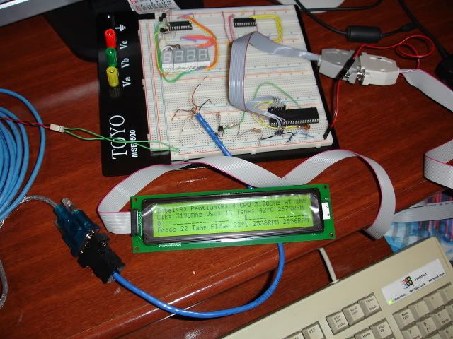
I've got 4 buttons (properly debounced, non-repeating) and 2 GPOs working on the PIC16F628, with LCD in 4-bit mode, PWM backlight control and proper buffered serial receive (19200baud via MAX232). All IO is used (no multiplexing). I currently only have a 4x20 backlit LCD which I'm building into a self-contained enclosure which I'll have on the desk somewhere, powered from the PC. The circuit is all on breadboard at the moment but I'll squeeze it onto veroboard in the enclosure.
The implemented commands are pretty much as per previous posts, with the addition of the GPO on/off commands.
Current schematic and C code/hex (HiTech PICC) available here (ZIPped source, hex, schematic)
Matt
I've been doing some more work on my MO serial implementation, after a lapse while moving house...
I've got 4 buttons (properly debounced, non-repeating) and 2 GPOs working on the PIC16F628, with LCD in 4-bit mode, PWM backlight control and proper buffered serial receive (19200baud via MAX232). All IO is used (no multiplexing). I currently only have a 4x20 backlit LCD which I'm building into a self-contained enclosure which I'll have on the desk somewhere, powered from the PC. The circuit is all on breadboard at the moment but I'll squeeze it onto veroboard in the enclosure.
The implemented commands are pretty much as per previous posts, with the addition of the GPO on/off commands.
Current schematic and C code/hex (HiTech PICC) available here (ZIPped source, hex, schematic)
Matt
-
_X7JAY7X_
- Hardware Genie - Plugin Author
- Posts: 374
- Joined: February 16th, 2005, 10:24 pm
- Location: Michigan
I had some freetime so I finally posted my newest firmware and schematic online. It is version 2.2 and it supports 4 buttons with minimal additional external parts over version 2.1.
http://www.freewebs.com/x7jay7x
J
http://www.freewebs.com/x7jay7x
J
-
pasan
- Posts: 54
- Joined: March 13th, 2007, 11:52 am
- Location: Sri Lanka
Nice work bro thank u very much. Im going to make it for my 16X2 LCD._X7JAY7X_ wrote:I had some freetime so I finally posted my newest firmware and schematic online. It is version 2.2 and it supports 4 buttons with minimal additional external parts over version 2.1.
http://www.freewebs.com/x7jay7x
J
Hey how to put a internal start up message .
