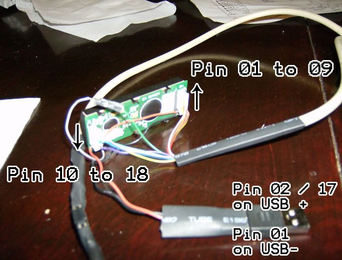
Its a 4x20 LCD with a Blue Blacklight. It have 18 Pins.
URL DATASHEET.
http://www.lcd-module.de/eng/pdf/doma/dip204-4e.pdf
PINOUT:
01. VSS (GND)
02. VDD (+5V)
03. VEE (Contrast adjustement,input)
04. RS(CS) (H=Command,L=Data)
05. R/W(SID) (H=Read,L=Read)
06. E(SCLK) (Enable (falling edge)
07. D0(SOD) (Display Data,LSB)
08. D1 (Display Data)
09. D2 (Display Data)
10. D3 (Display Data)
11. D4 (Display Data)
12. D5 (Display Data)
13. D6 (Display Data)
14. D7 (Display Data)
15. -- NC
16. RES Reset (internal Pullup 10k)
17. A LED B/L+ Resistor Required
18. C LED B/L-
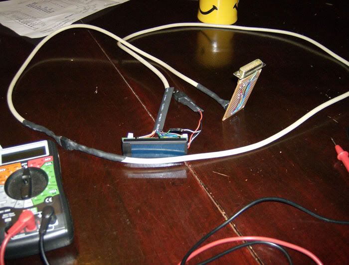
I search a way to connect it on LPT i see 2 diagram :

and

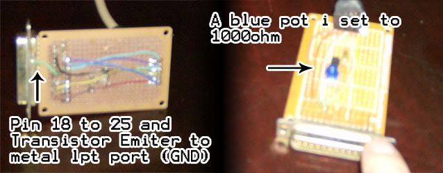
I buy the part for the two diagram.
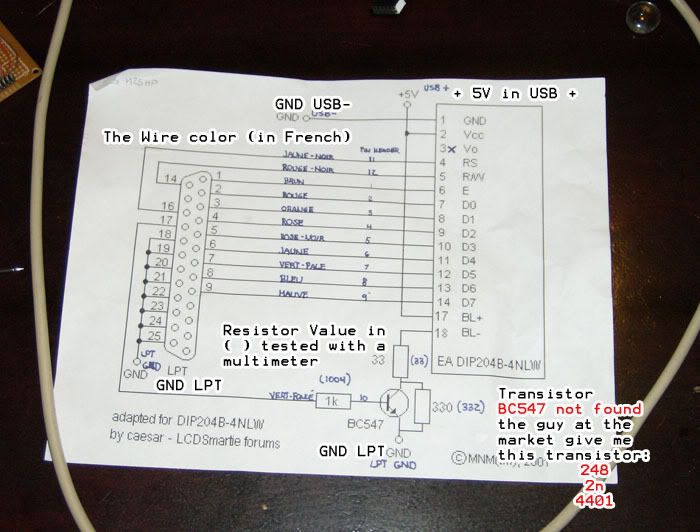
but when i going to assemble it i see on the datasheet :
CONTRAST ADJUSTMENT
PIN 3 Require driving voltage for contrast VEE.
4NLW model have a built-in temperature compensation;so there's no more need for contrast adjustment while operation anymore.
I see a diagram with VEE enter a pot of 2.5k and to to VDD.
I see
iam not really good to understand this kind of doc. Iam a really good solder and programmer but for the electronic..hmm.BLACKLIGHTUsing the LED Backlight repquire an current source or external current-limiting resistor.
yellow/green backlight is 3.8-4.2v ad for white LED backlight is 3.0-3.6V.
Blue-White displays do always need a backlight for contrast(min 5mA).
I dont know if the Voltage is the same of the White Backlight.. and the contrast stuff give me a headache.
It is possible to someone to give me the correct connection for my LCD and the correct Resistance. for this one if possible. http://lcdsmartie.sourceforge.net/LCDconnect.jpg
i don't want to scrap the LCD hehe.
Thx alot and sorry for me horrible english