having read a few posts about buttons i thought i can but ask this
I have a 4x20 LCD on a parallel port can a button be added to this to be programed to show next screen?
if so that wiring should be added?
the reason is simple, i use a screen to tell when email is waiting and is set to sticky but skip if no new email and think a button on case to act like a reset to say i have cleared the email, and the go to next screen owuld be the logic way ( as thats what i do at the moment) but would rather not have to open program from tray, hit next screen, then minimise.
Our new official repo is on github
LCD Smartie version 5.6 is released!
Download it now: https://github.com/LCD-Smartie/LCDSmartie/releases
LCD Smartie version 5.6 is released!
Download it now: https://github.com/LCD-Smartie/LCDSmartie/releases
adding a button to a parallel port LCD?
Moderators: _X7JAY7X_, caesar, IFR, mattcro, limbo, Fast351, hydrolisk1792
-
riffraff
- Posts: 18
- Joined: April 8th, 2007, 1:48 pm
- Location: Fife, Scotland
-
limbo
- Plugin Author
- Posts: 1604
- Joined: February 13th, 2005, 7:38 pm
- Location: Athens - Greece
- Contact:
If you 're using a PC and not a HTPC you can use also global hotkeys for this.
For external buttons use this link http://forums.lcdsmartie.org/viewtopic.php?t=876&
For external buttons use this link http://forums.lcdsmartie.org/viewtopic.php?t=876&
Last edited by limbo on June 24th, 2007, 9:57 pm, edited 1 time in total.
-
mattcro
- Forum Supporter
- Posts: 590
- Joined: March 8th, 2006, 1:58 pm
- Location: Scotland
You'll probably get it to work by simply wiring a switch between an input pin (10-13) and ground (any of pins 18-25).
If that doesn't work, you might need to add a pull-up resistor of a few kiloohms (try 10K ohms) between the input pin and +5V, as shown further down the post limbo linked to.
If that doesn't work, you might need to add a pull-up resistor of a few kiloohms (try 10K ohms) between the input pin and +5V, as shown further down the post limbo linked to.
Last edited by mattcro on June 24th, 2007, 6:05 pm, edited 1 time in total.
-
riffraff
- Posts: 18
- Joined: April 8th, 2007, 1:48 pm
- Location: Fife, Scotland
having already made the lcd connection below MINUS the red boxed section i was just about to start the slodering when i go your post.
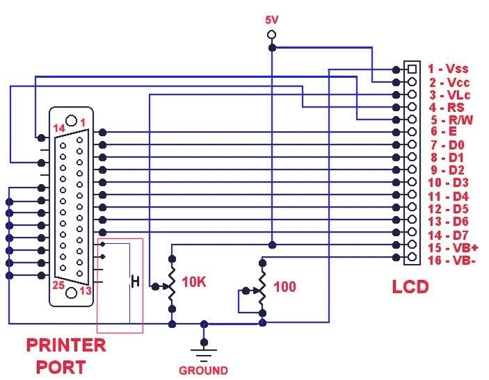
same pic as mentioned in the post but reduected down to 1 switch
the red box shows a link between pin 11, switch then to the NEG (black) PSU/ Molex connector which is also connected to pins 18-25, or am i reading that wrong,
same pic as mentioned in the post but reduected down to 1 switch
the red box shows a link between pin 11, switch then to the NEG (black) PSU/ Molex connector which is also connected to pins 18-25, or am i reading that wrong,
-
mattcro
- Forum Supporter
- Posts: 590
- Joined: March 8th, 2006, 1:58 pm
- Location: Scotland