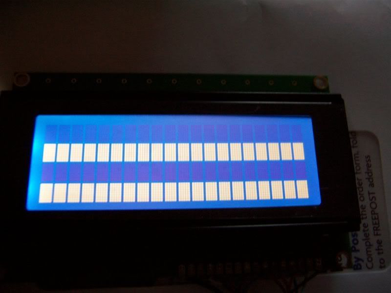
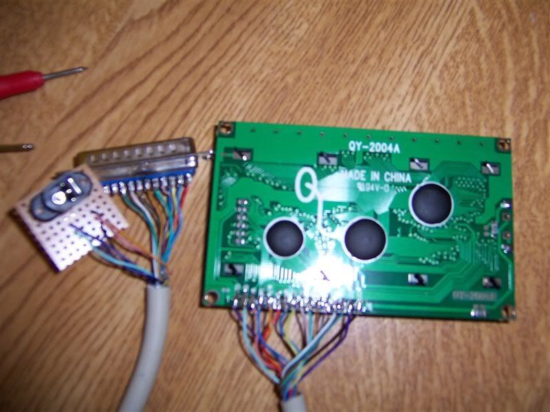
I'm trying to set up an LCD on my machine. I have the unit pictured below (I got 3 actually). I have double checked all connections with my DMM and they are all correct, the display shows the 2 test blocks/lines when powere is applied.
When I run LCD-S and configure the settings i.e. HD44780, LPT1/$378 etc it still displays the same test screen. I have tried on 2 of my PC's and a laptop with no success. All tests have been done with EPP, ECP, Normal and Bi-Directional Parallel modes in the BIOS and the device manager settings show LPT1/378,
Is there anything else I should check? As I have been trying for days.
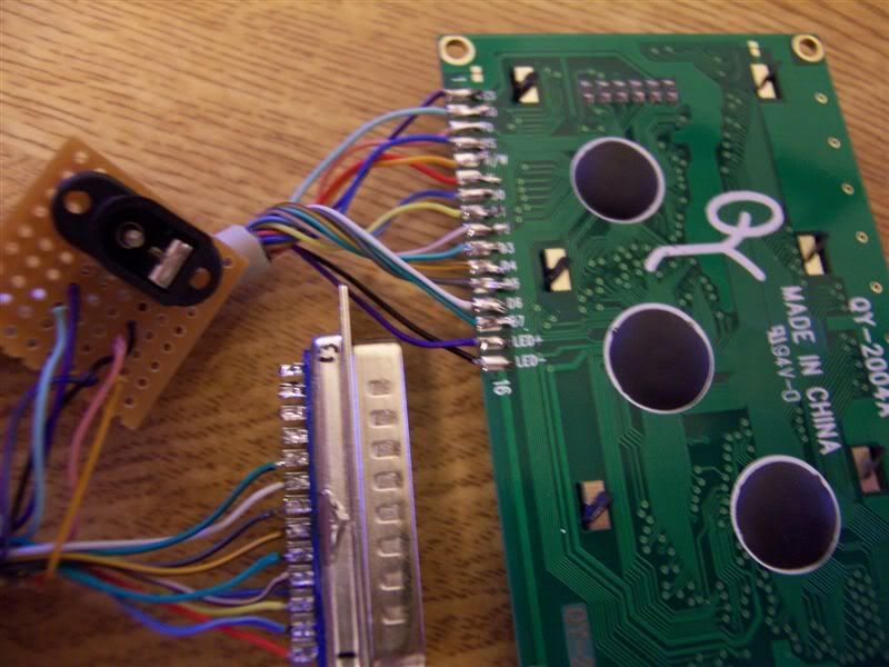
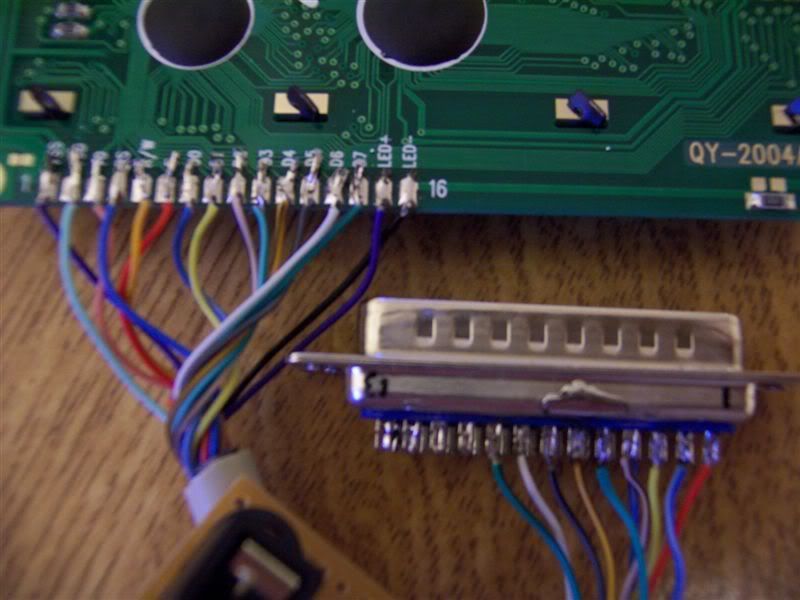
It's difficult to tell from the photos, but it looks like you have only 10 connections to the parallel port connector. There should be 12, so check against this schematic (the first diagram).
You might be missing the R/W (pin 14 on parallel connector) and ground (pin 18 ) connections.
Last edited by mattcro on March 20th, 2007, 8:55 pm, edited 1 time in total.
I'm using this diagram. and it's wired exactly like this but rather than using a molex connector I'm using a regulated 5v supply. Does the ground need to be to the D-Sub plug?
If you're using a separate power supply (not from the PC) you need to connect the LCD ground (pin 1) to the parallel port ground (pin 18 ). Your schematic should work if you use the PC's power supply because then everything would be connected to the PC ground.
I think you will also need to connect the LCD R/W (pin 5) to parallel port pin 14 (as per Smartie schematics) instead of ground as in your schematic.
Last edited by mattcro on March 21st, 2007, 11:20 am, edited 1 time in total.
Just to clarify, ground on an LPT port is pins 18-25, not pin 1 (that's strobe if memory serves).
Your power supply power and ground need to be tied to the display, and the display needs to have ground going to the PC (in essence hooking your PS ground to your PC).
From your diagram, it looks like none of 1,3,5,14 are grounded to the PC. My guess is if you tie the common ground to pins 18-25 on your LPT port all will be fine.
Thanks peeps, it was because the PSU was not grounded - pretty obvious when I think about it lol. When using a 5v (4.5v) PSU all blocks went white, dropped it to 3v and it's working a treat. Might add the pots later once it's in its case.
Whoever drew that schematic should have been thorough and included the ground connection to the parallel port .
You probably need to add the contrast pot to allow some adjustment. That could be the cause of the "white blocks" with the supply at 5V. The contrast will reduce as the supply voltage is reduced (IIRC).
The LCDs I've used all needed the contrast adjustment because the contrast was too high with the pin connected directly to ground. The optimum setting varies with viewing angle too, so it's probably a good idea to add the pot. You can also use a single fixed-value resistor between the contrast pin and ground. Somewhere around 1k works well, IIRC.
Hi, I am having a similar problem. If I power up the lcd I get the same two lines of lighted blocks. What I don't get is some info on the lcd.
The lcd I am using is this
and the schematic is the same as provided on that link, it should be the same as on the lcdsmartie page.
What could be the problem?
One more thing. While connected to the laptop, it lights up very dim (it gets ca 2.5v out of my laptop lpt). When connected to my pc then it lights up all the way, as if it didn't need an external power supply (by adding one, it'll just get a bit brighter). By turning the 10k pot I can get the white blocks to disappear.
You do need an external power supply of some sort (+5V) for the LCD to work properly. The LPT (parallel) port isn't supposed to supply any power to the LCD, only signals.
The schematic shows a 5V terminal. This should be connected to the 5V power supply, not to the parallel port. You can get the 5V from a spare disk drive connector inside the PC (red cable is +5V, black cable is Ground/0V), or a separate regulated (NOT unregulated!) power supply.
Yeah, I have the 5V external power supply connected.
Now I tested it on a win 2k machine and it was working well :S
None of the tested Win XP machines seem to work although I installed the port95nt.exe. How can I solve this issue?
I'm desperate.
-edit-
Solved the problem :phew:
Gave another look at the ports and it seems that IBM T43 had a different port address, after changing it to EPP and 378, it worked fine.
On the other machine the problem was that LPT1 was the parallel port on the motherboard, but my LCD was connected to a pci parallel port adapter with port number AC00.
Feels great to have got it to work properly